I’ve had several requests to write a how-to for my dual battery set up and I finally got it put together. Thanks to chrishaynesusa for keeping my butt to the fire, and the others that have encouraged me to write it up. I hope this helps!
A couple things to keep in mind:
1. This project is really two projects in one, moving the power steering fluid reservoir and adding the additional electrical.
2. The electrical changes are not particularly difficult but anytime you work around batteries there is a hazard associated with it. Be careful.
3. Because I’m that kind of person, I installed a high-end version that is completely unnecessary, so I will try to differentiate what is really important vs what is actually necessary.
4. Because there are about 40 pictures associated with this write up, I had to link to my Photobucket site instead of interleaving the pictures with the text. Sorry. That also made it easier for me. Go here for the pictures:
http://s812.photobucket.com/albums/zz46/CampCroker/Xterra stuff/Dual Battery Install/
OK, let’s get to it….
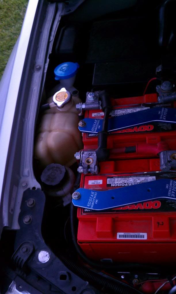
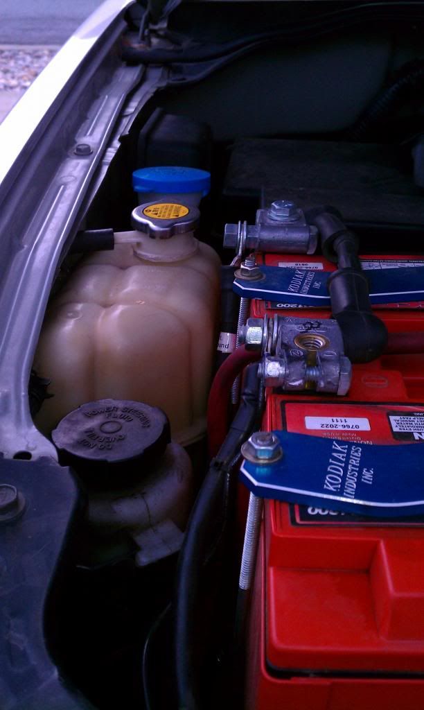
PROJECT 1 – RELOCATING THE POWER STEERING FLUID RESERVOIR (PSFR)
1. Remove the battery.
2. Lift the PSFR off the bracket. It is tight, but it should go. I forget if I had to remove any tabs or ties. (pic2)
3. Unclip voltage monitor from bracket. That let’s you remove the bolt from the top that holds the main battery ground bracket to the reservoir bracket. Remove ground bracket from reservoir bracket and remove the ground bracket from main ground cable (leave the clamp on the cable). (all 10mm)
4. Remove the 3 bolts that hold the reservoir bracket, and save them (all 10mm) (pic3)
5. Time to remove the PSFR and hoses. You’ll want to have two empty 16oz bottled water bottles handy to collect the power steering fluid that will leak out. I removed the supply hose (the smaller of the two) from the reservoir first. Quickly place a bottle under the reservoir nipple and let it drain, meanwhile holding the supply hose up so it doesn’t leak. Once the reservoir is mostly empty, I put a piece of duct tape over the nipple to prevent more dripping. I then removed the return hose (the larger of the two) from the reservoir and added a piece of duct tape to that nipple too and set the reservoir aside. Next I removed the supply hose from the metal “hose” coming from the pump (just to the right of the battery tray). This effort is the first place where swearing might occur because it is a tight fit. I had my wife help by holding the free end of the hose while I worked on getting the hose free. I had the other empty water bottle down inside the engine bay nearby so I could quickly throw it on the metal hose end once the hose was off. A few drops of fluid came out the newly freed end of hose before we could turn it up to prevent more leaks. Then we emptied the supply hose into the first water bottle and set those aside. The second bottle remained on the end of the metal hose until I was ready to install the new hose. Eventually there was about 2-3 ounces of fluid drip into it before I was done. The last step is to remove the return hose from the engine block. I had no fluid drips with the removal of this hose. I then placed another piece of duct tape over the metal nipple on the engine so no foreign particles would accidentally fall in. The two hoses cannot be reused. I don’t have any pics of this step because a) I was too occupied with hoses leaking fluid and b) my hands were too slimy. Sorry.
6. Find the unused slotted bracket by the manifold and drill it out to ¼” (circled in pic4)
7. Find a bracket that you can use for a riser for the PSFR bracket about 1.5” to 2”. I used a Simpson Strong Tie bracket I had laying around. (see pic5 and others later). Drill out the riser bracket to hold the PSFR bracket and so it can also attach to the slotted bracket from step 6. Install as in pic5 so that you can measure for another support bracket shown in pics 6-8.
8. Cut, drill and bend additional support bracket. (pic6) I used a plated steel strap 1” wide by 1/8” thick by 4 1/8” long. One end attaches to the PSFR bracket and the other end to a threaded hole that is not being used closer to the front of the vehicle. (pic7-8) This hole accepts 10mm bolts.
9. Assemble the original PSFR bracket, the riser bracket, and the additional support bracket with ¼”-20 SS bolts (mostly 1” and ½” long). Mount bracket assembly to the vehicle using a ¼”-20 bolt at the slotted bracket from step 6 and one of the 10mm bolts you removed in step 4. Final bracket assembly in pic9.
10. Remove the large wiring bundle from the restraining clamp shown in pic 10 and the bracket that holds it in. You’ll use this same hole (from the bracket) for your own hose clamp in step 12. Also remove the ground lug (two black cables from large wiring bundle—also pic 10). Bend the wiring harness back to give you more room to route new hoses.
11. Attach the new return hose (9/16” ID, 15/16” OD; p/n Gates 85965F—difficult to find—which is actually hydraulic fluid hose) to reservoir and measure length allowing for bends and clamps. Mine was 21”. Attach the new supply hose (3/8” ID, 11/16” OD; p/n Gates 350010F which is regular power steering hose) to the reservoir and measure the length allowing for bends and clamps. Mine was 29”. Note: I allowed for slack in both hoses to allow me to still slip the reservoir out of the bracket for future access to the engine. Cut hoses to length. Once the hoses are the correct length, put reservoir in its bracket and feed the hoses through a final time. The return hose will slide on easily but the supply will not. Lube up the supply hose with a little power steering fluid and get ready to swear again. The metal hose is loose enough I blocked it with a wood block to allow me to push harder without damaging the metal hose. Make sure you have the spring clamp on before you do this! Secure all hose ends with the original spring clamps and secure the reservoir in its bracket (I used one long tie wrap around the whole assembly to get it to sit down).
12. Secure the new hoses to the frame with rubber-insulated clamps (1” size for return hose, 5/8” for supply). Use the 10mm bolts that you’ve saved to attach the clamps to the frame. (Pic11)
13. Protect the new hoses with flex tubing where necessary to avoid unwanted rubbing. (Pics 12 and 13)
13a. Refill the PSFR! It took about a bottle and a quarter for me.
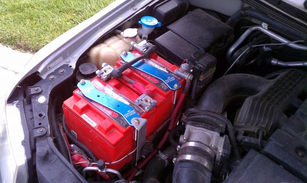
PROJECT 2 – BATTERY TRAYS AND ELECTRICAL
14. Make room for the aux battery tray. Remove the flange where the battery tie down J-bolt in front used to attach. I don’t have a cut off saw, so I just used brute force, a chisel, and a hammer to essentially rip the flange off. It’s held on by a couple tack welds. If you have a chop saw, that’s probably the way to go. (pic14)
15. Drill a new hole in frame for the new battery tie down J-bolt (pic15). Because the drill will be at an angle to the smooth metal and a hole punch is difficult to get through the hole, start with a small bit and work your way up to a 5/16” hole. The bit will go through an existing hole (see pic15). Of course if you have an angle drill, this step will be easier as you can come at it from the outside. The new J-bolt will only be ¼” but a 5/16” hole makes it easier to slip the bolt into.
16. Install the inside battery tie down point. I used a 2” plated steel angle bracket and cut one side down to 1” (pic 16). The holes in the bracket were already basically 1/4”, but I reamed them out by another 1/16” or so. Attach the bracket to the frame through the existing hole near the relay box. You’ll have to drill a ¼” hole in the plastic wheel well lining. Use ¼” stainless steel bolt and hardware.
17. Fabricate new battery trays. NOTE: If you use different batteries, your dimensions will be different. Follow along for the concept. I used an Optima Yellow Top for my main (starter) battery and an Optima Blue Top for my auxiliary battery. Turns out using the Optimas was advantageous due to the rounded corners that allowed for support bolts in the corners and ends of the trays. Other batteries can work, but you’ll want to spend A LOT of time figuring out if there is room for your style/size of battery and the support bolt system I describe will probably have to be worked around. I suspect a Red Top will fit just as well as a Yellow Top for the main battery. The material I used for the trays was 1/8” thick stainless steel plate from a local supplier.
17a. Main battery plate: Dimensions are 10” x 7.5” on the outside. See pic17 on how I marked the plate to cut the corners out and then rounded the remaining corners and filed all edges to eliminate sharp edges (pic18). Bend up the sides as shown in the pics. Drill 4 holes: 2 for attaching to the frame and 2 for support bolts (pic19). The support bolts are ¼” x 1 5/8” long. Pic29 shows the tray mounted, but you don’t want to mount it permanently just yet.
17b. Auxiliary battery tray: Dimensions are 11.75” x 7.75” on the outside. See pics20-23 on how I marked, cut, bent, and drilled the plate. The support bolt is ¼” x 5.5” long which goes in the front left corner. I also added an angle bracket to the right side of the tray on the underside to help support the right side of the tray. The bracket just rests against the frame to the right of where you drilled the new front J-bolt, and just helps keep the right side of the tray from bending so much. This may not be necessary, but I think it also helps hold the tray in place. Pics 24-26 show the aux batt tray assembled. Pic 31 shows the tray mounted to the frame, but don’t do that yet.
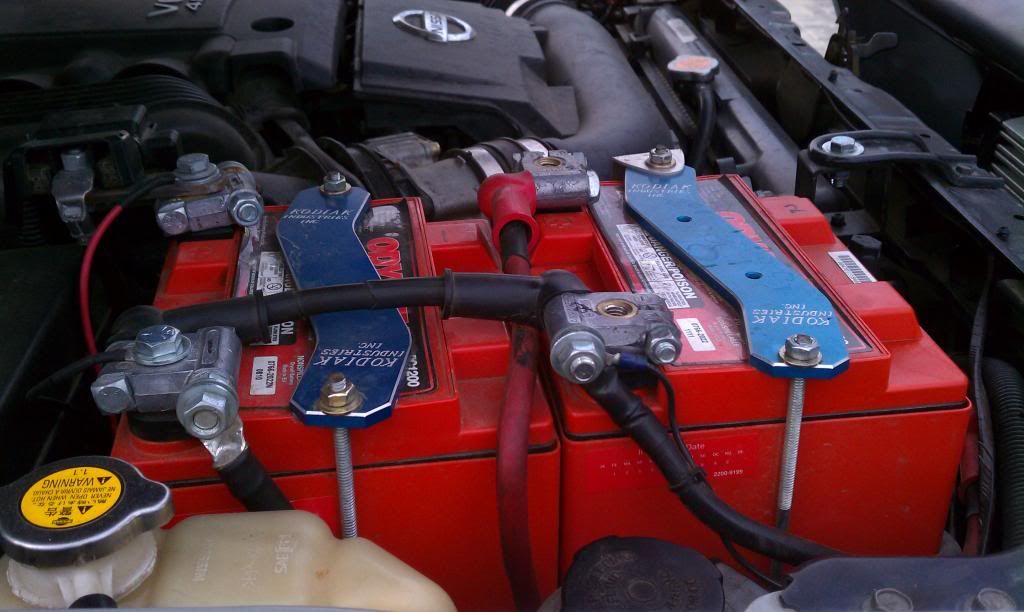
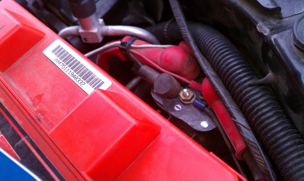
18. Trim back split loom tubing on large wiring bundle that goes to the positive battery terminal to allow more slack on the two ground wires that are part of the bundle. Cut a 9” long piece of #4 AWG wire, and add ¼” lugs to both ends. Add new split loom to both the new #4 wire and the original two ground wires. Use a ¼” x 1” long stainless steel bolt to connect the original ground wires and one end of the new #4 wire to the angled ground clamp on the negative battery lead. (pic27). Use one of the 10mm bolts you’ve saved to attach the other end of the new #4 wire to the frame (I cleaned up the bolt hole area with a wire brush on a Dremel to ensure a good electrical contact). Cut off the very end of the cheesy negative battery terminal and crimp on a new #4 x 5/16” lug. This lug will fit on the new negative main battery terminal that you purchase. (see pic36)
19. Follow the main negative lead back to the engine block and unbolt the main bolt (12mm). Install a new #2 AWG wire with a 5/16” lug on one end (to fit over the 12mm lug) to that main engine block ground point and bolt the two ground leads under the one 12mm bolt (make sure the OEM lug is shiny clean and clean the bolt). The length of the new #2 depends on whether you do the simple install or the high-end install that I did. I used a piece about 24” long to thread between the two batteries to the negative power post. For the simple install, the other end of the wire can go straight to the negative terminal on the aux battery.
20. Remove the positive battery terminal from the large harness that includes all of the fuses (cheap piece of crap). I had to soak the bolt for a while to get it to break free. Thoroughly clean the plate that it attached to. (pic28) (For high-end install only) Remove the alternator lead from the positive battery fuse harness (it’s the one on the left that feeds the 140A fuse). You’ll need to cut the alternator wire back an inch or two and add a new #2 x 5/16” lug.
21. Install the main battery tray. (pic29)
22. (For high-end install only) Build a wood board as shown in pics30-32 to attach the negative power post and (if wanted) shunt. My pics show a solenoid attached on a piece of wood in the vertical position. The solenoid is part of the Warn Quick Connector remote cut off switch that mounts inside the cab. If you don’t have one or care to install one, ignore that part of the build. I protected the wood with a couple coats of clear acrylic. This board and the aux battery tray share the same hole in the frame.
22a. (For high-end install only) Install negative power post and (if wanted) shunt to board (this shunt is used to monitor the current flow to or from the aux battery). Install copper strap between power post and shunt and protect it with shrink tubing. If you have a solenoid like me, install it now.
23. Install aux battery tray and (if used) wood block from step 22. This requires drilling a ¼” hole through the frame into the wheel well. After drilling the hole, I used that as a guide to cut away more of the plastic lining inside the wheel well with a utility knife so that the bolt head (1/4” x 1” or 1.5” depending on whether you installed the wood block) and a nice big washer can sit flush with the frame. (pics30-33)
At this point, it is hard for me to describe what to do because everyone will have a different reason for adding a second battery. I wanted an aux battery mainly to run accessories like a 12V fridge, comm. radios, and my air compressor. I also added the shunts for monitoring current and voltage and a solenoid to remotely turn on and off my Warn quick connectors front and rear.
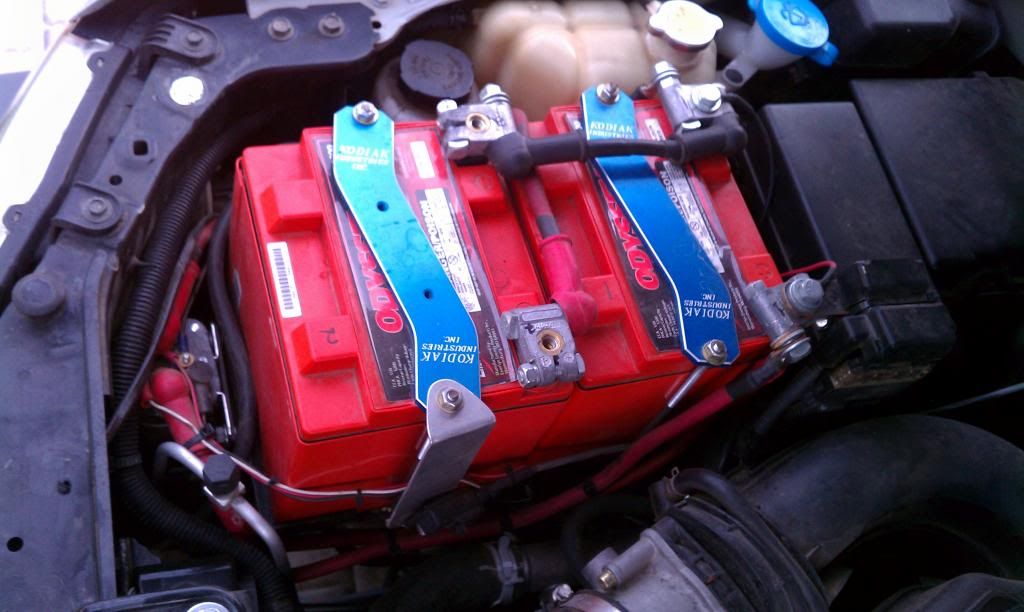
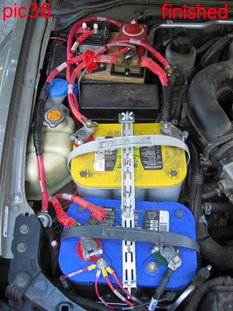
In pics 35-37 will show the final electrical hookup that I did. Diagrams 1 and 2 show my wiring diagram and a simplified wiring diagram respectively. Wiring diagram 3 shows the alternate grounding scheme that I’m considering trying due to the Variable Voltage Monitor complication (have not tried it yet ). The wiring diagrams have fairly complete parts lists, at least for the major items. I know they are missing some things.
I will, however, describe the battery tie-down that I came up with because that will apply to everyone:
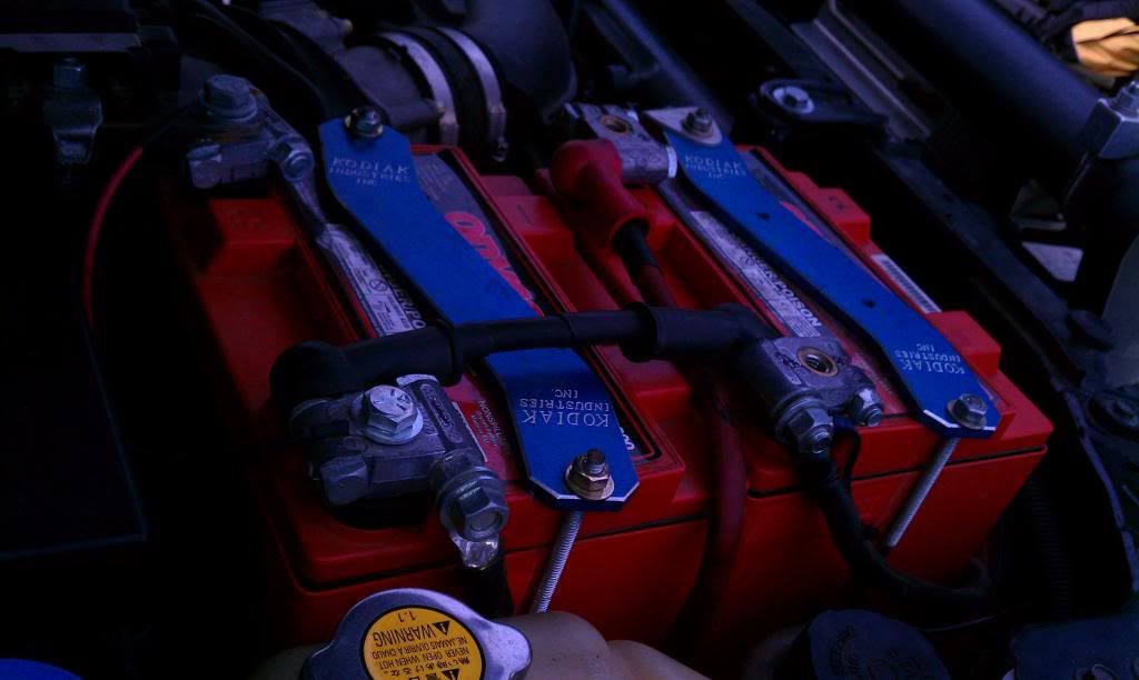
24. Buy new 8” and 10” J-bolts. The 10” is for the front and the rear is 8" (the measured length of the rear bolt is 6.25” after I cut it down, so you might be able to get by with a 6” J-bolt instead). I used double-slotted closet shelving rails that I had laying around, and they worked great. Cut two lengths, one 6.75” long and the other 9.25” long. The 6.75” piece goes over the aux battery, labeled “blue side” in pics 36 & 37. Drill one hole at each end of each piece to accept the J-bolts. Then drill 2 holes in the other ends of each piece that line up with each other. Note the orientation of the brackets in the pictures as they are opposite each other. Use 1.5” long ¼” bolts with extra nuts and washers to bolt the two pieces together (pic38). Lastly, I had to cut and drill a short piece of metal strapping for the wing nut on the rear J-bolt (pic36).
More notes in a follow-up post. Cheers!

")